
Atari Pong Arcade Repair Log Advice and Tips
- Cassie
- Feb 21, 2021
- 12 min read
Updated: Oct 8, 2023


Attempting to write fully on the legacy of Atari’s Pong would be a hard-fought assignment for even the most knowledgeable classic arcade game aficionado. In this guide, I will just say on the topic of the legacy of Pong in my opinion, it is the most important arcade game machine in history. Despite armchair video game fans often misstating that Pong was the first arcade game (it wasn’t, that would be Computer Space), it was the first successful one and more importantly the first game to have crossover appeal outside of computer hobbyist or technology chasers. Pong was a phenonenom and started the video game craze as we know it.
Pong would also be the cornerstone of the corporate legacy of Atari, the almost folklore aura surrounding Nolan Bushnell, and set the tone for the industry to come. This page is dedicated to helping those lucky souls with surviving machines to hopefully get them up and running again. Working on my Pong machine I was somewhat surprised by the lack of information about the internal running mecanics or troubleshooting of the machine so hopefully this will help others going down the same path.
How Many Pong Machines Were Made?

Exact figures on Atari’s Pong production are unknown to us, I have heard production figures as high as 20,000 and as low as 5,000. I personally feel a number somewhere between 7,000 – 9,000 is probably realistic. If this seems like way too few for a game that would become a pop culture icon you have to consider a few factors. First, Atari was a new company with limited production capability when Pong was released. Atari could have never guessed that the very first game they would release would go onto become such a smash hit, and they ramped up production the best they could at the time. Second, distribution for amusement machines was very regionally locked in the 70’s with exclusive contracts for some regions of the nation. In a nutshell what this means is that due to these contracts Atari couldn’t sell their machines easily or sometimes at all in certain areas of the country. This is why soon after the release of Pong, Atari would form a second company called Kee Games in order to circumnavigate some of these distribution issues. Third, Pong was expensive to buy when compared to pinball or electromechanical games of the era. And lastly, the huge wave of Pong clone machines (which started coming out mere months after Atari’s Pong) ate massively into the market. Many of these companies had much greater manufacturing capabilities than Atari (Such as Allied Leisure in Florida with their Pong knock off “Paddle Battle”) and had established distribution relationships.
Deciphering Pong Serial Numbers

Atari used an unusual system for serial numbers for Pong in an attempt to hide the actual numbers of machines manufactured from the competition. This numbering system is not only baffling, but Atari often skipped numbers chronologically making knowing exact production figured impossible now. The serial numbers have a three letter and then three number combination starting with ZZZ-000, then after ZZZ-999 Atari would switch to the front of the alphabet to AAA-000 – AAA-999… then back again to YYY-000 and so on. My guess is Atari had some sort of “Matrix” to decode the actual serial numbers in chronological order but unfortunately this information has been lost to us over time. Future Atari products would carry more traditional serial numbers.
Cabinet Differences

There was at least one major change and several small changes in the Pong cabinet design over time. Around the halfway point of production, the bottom edge of the cabinet was changed to eliminate the stylist “cut in” to a straight edge to improve stability. A word of warning that I found out the hard way, if your cabinet is one of the early styles with the cool cut in at the front base it is very easy to tip over the cabinet. Don't be a knucklehead and give yourself a heart attack by almost destroying a piece of arcade history... be careful! I would recommend placing a large brick or two in the bottom back of the cabinet for stability protection.
I have also seen photos of some cabinets with metal “rails” attached to the bottom, but I don’t know if this was an official fix for this problem or was just an operator being crafty on their own accord. The control panel also went thought at least one variation with a change of fonts from the Microgram style font to more of an Ariel style font at some point. Knobs on the control panel also changed over time and appear to have changed several times. There is a bit of controversy over which knobs are “the real Pong knobs” with collectors. Knobs easily “walked off” and it is possible operators replaced the knobs with whatever they had laying around. I found some great reproduction vintage style knobs for my Pong machines that seem to be a great stand in.

The coin mechs changed from a single generic style to almost a “Midway” style coin door in later models, which removes the inner coin collector tray which itself is actually a legitimate loaf cooking pan you could have bought from any grocery store in the 70’s. Internal placement of the isolation transformer and fuse holder seem to vary from machine to machine with little rhyme or reason. Some games have a small wood platform holding the TV to ensure the correct height of the TV screen with the game bezel. Early bezels are made of cardboard which deteriorate easily (and was simply taped to the TV using black Gaffer tape) with later machines having a much stouter plastic molded bezel.

Optional stickers were provided by Atari and taped into the inside of the machines for operators to stick on the glass. These stickers stated the game either ended at 11 or 15 scored points for a player depending on the operator’s dip switch preference on the PCB. An additional dip switch was planned at position A1 on the board to allow either a slow or fast initial serve, but this feature was not included in production models. Real Atari Pong PCB boards will be marked as “PONG SYZYGY E” near the A1 position, Syzygy being the original name for Atari. Early PCB’s will have the large capacitor near the edge connector sitting upright, later versions the capacitor will be laying down flush with the board. Some “unofficial” or bootleg Pong games that copy this board design to a tee, may have additional sub boards such as ones that modify the game speed, or set a timer for 5-7 minutes per game. Many of Atari’s PCB’s for games from 1972-1975 share a very similar design and use similar components to Pong. Pong does not use a microprocessor, ROM, or RAM. A majority of the game IC’s are simply gates.
Pong Wiring Harness and Power Supply

The wiring harness and internal power supply to Pong is extremely simple. The power chord feeds into an isolation transformer, feeding out to the power for the TV and one fuse. There is no power switch on a Pong machine, and most of the power supply elements are actually built into the Pong PCB itself. One modification I made was to not plug the TV directly into the isolation transformer but instead installing a small fused multi plug in the bottom of the machine so I could both plug in the game and the TV separately and have an on/off switch. The edge connector feeds the power to the PCB, inputs from the paddles, coin mech, coin counter, and video/audio feeds to the TV.
PCB Chip Location and Trouble Shooting Guide
There are some fantastic resources for understanding the operation and brilliance of the Pong design on the web. I highly recommend checking out ATARI PONG E CIRCUIT ANALYSIS & LAWN TENNIS: BUILDING A DIGITAL VIDEO GAME WITH 74 SERIES TTL IC’s by Dr. H. Holden for a very detailed and scientific approach to understanding both Pong and early IC design. Pong is a great teacher for those wanting to get deeper into understanding how the logic of early (and even later) arcade games function. It also offers a much more detailed synopsis on the workings of Pong than will be listed here.
Below you will find a listing for trouble shootings of various IC’s, the locations of those IC’s and what exactly they do or don’t do on the Pong board. This is adapted from a few manuals (including the excellent manual for Winner by Midway, a direct Pong clone) and from my own attempts to fix Pong boards. I was pretty lucky with a few go arounds with a logic probe and replacing of three IC's I was able to get my Pong PCB working correctly.

If the original capacitors on your PCB are the original ones, it may not be a bad idea to change those either. If you can’t seem to get your paddles from being “jittery” after replacing the pots on the controllers (which are 1k, linear pots) try replacing the adjustment pots on the PCB itself (these are 50K pots).
Other wierd issues I ran into?
If the game starts but no ball comes out, check the ground wires from the harness.
If a ground is not connected to the paddles or coin mech it can cause the game not to start correctly for some reason.
Audio is super buzzy but you have checked the IC's? Check the capacitors on the PCB, they probably need to be replaced.
A earth ground can also help with this audio issue, and make sure you have a grounded plug on the game as well.
Game doesn't respect the bottom or top virtual net but still makes the beep noise like it does? Replace the IC at B6.
The video screen is sort of more to the left? This is normal for real Pong PCB's. Try to adjust the controls on your TV to help a bit.
What to do when you can’t locate a Pong PCB
Pong PCB’s are getting more and more difficult to find, with fully working ones commanding decent money. Although if you are lucky enough to find even a non-working original Pong PCB, there might be some cases despite the rather basic nature of its design it may not be repairable. Several industrious arcade aficionados have over the years created reproduction PCB’s with some success. There is good news however for those of you wanting to fix that empty Pong cabinet you found in a barn or those truly dedicated collectors building a game from scratch needing to source a PCB. The large amount of Pong clone machines during the early 1970’s from dubious manufactures offer a bright spot for you, most of the PCB’s from these machines are carbon copies of the original Atari Pong design right down to the edge connector fonts.

With all that is mind, many Pong copycat and bootleg PCB’s are exactly like the Atari version and completely compatible with an original Atari cabinet. Chip locations and types are exactly the same as well, and the advantage is these PCB’s are often unloved and unwanted by collectors. Below you see two such PCB’s that I picked up on eBay for less than 50 dollars each. The first one is Midway’s Winner which I think was actually an officially licensed Pong copy. Even though it was missing a few chips it was in nice shape and should be easy to repair. The second one is called Rally by a company known as Four Play (or 4 Play?) which by some accounts was actually the first Pong clone to market. Again, the PCB is exactly the same as an original Pong machine down to the switches used and the font on the edge connector. It is amazing how bold some of these manufactures were with freely copying other people’s products back then.
One important note here though if you attempt to use a bootleg Pong PCB in a Pong cabinet, you are probably going to have to carefully look and change out the capacitors. Most bootleg or Pong copy boards used different additional power supply boards or other systems for power, so tread lightly and carefully when doing this.
How to Connect the TV to the Pong Cabinet

All Atari Pong machines used off the shelf small 12 inch Black and White televisions of the era, literally the same TV’s anyone could go to their local Sears and buy for around 100 dollars in 1972. Late model Pong machines seem to have bare monitor chassis without the TV tuners and plastic TV cases, but most Pong machines were shipped with regular old commercial TV sets. Brands of the TV sets can vary although it seems a majority of them were Toshiba or Mitsubishi models. Atari would also remove the channel knobs off the TV's in the factory once they were set up. The TV set that came with my Pong looked like it had been in the bottom of an ocean for the last 20 years and was not repairable. The good news is 12 inch black and white televisions from this era are cheap and easy to find still. I found a 1975 version of the same broken 1973 Toshiba model that my machine had originally in practically brand-new condition for 60 dollars.

Connecting the Pong PCB to the TV is not as easy as it sounds, originally, I thought it would just connect much like the old Atari 2600 RF switch boxes, but I was living a terrible lie. The inside of the TV must be slightly modified in order for Pong’s PCB to play through it. The good news is this is a relatively easy procedure needing only the most basic of TV repair and electronics repair skills. In a nutshell these steps should get your TV modified for Pong…
*WARNING: Proceed at your own risk, I am not responsible for damage to yourself or equipment in any way. Electronics and electronic items should be modified and repaired by persons who are skilled and/or trained in the repair of sed items. *
1. Open up the TV case carefully (unplugged of course) , and I would recommend discharging the flyback for safety.
2. You need to disconnect the UHF and VHF internal and external antenna leads or wires that lead to the external connectors for the antenna hook ups on the back.

(Above Photo: This is the back side of the antenna connector plate, you can see the wire that connected both sides of the VHF terminals has been cut)
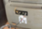
3. If there is a “bridge” wire or transistor on the backside of the UHF or VHF antenna leads, snip this. The antenna inputs will become the passthrough inputs for your video, sound, and ground to the monitor from the PCB edge connector. You want all antenna connections disconnected, and each UHF/VHF screw connector to be "its own thing" now.
4. Internally connect a wire from one of the antenna inputs to the internal video test point of the monitor chassis. This is normally on the main board and will bypass the video signal from the tuner. This might take a bit of exploring or if you are really lucky, you can find the old repair manual which can guide you. You are essentially overriding the receiver to feed only your signal from the Pong machine video.

(Above Photo: Here the arrow is pointing to the video hook up for this monitor on it's main board, you can see the black wire below is the ground connection which has been soldered onto a metal cover plate)
5. Next, Internally do the same for a ground input, you can ground the wire to any non-important non functioning metal part such as a chassis cage or metal cover, but I would strongly recommend keeping it away from anything near the main board or audio section for interference or possible shock issues.
6. Now connect your sound wire to the input wire on the volume knob of the TV itself. Be careful with this! Often these knobs are two stage knobs for power on and volume control, you want the non ground wire that controls the sound volume on the knob.
7. Now (remembering which input is which, I labeled mine on the back of the TV with a label maker) screw in the sound, video, and group wires from the PCB to the antenna inputs on the back of the TV. If you have done this correctly, the Pong PCB will directly connect to the video feed of the TV on any VHF channel although you may find one channel looks slightly better than another. The sound volume should be controlled from the volume knob of the TV.
8. If you are hearing a smallish hum in the audio and it doesn’t seem to be a PCB issue, installing a small capacitor between the audio input and the ground (oh like 47 ohms or so) should help dull this down.
9. Turn the contrast up on the TV but the Brightness down, this should get rid of any odd interference issues in the playfield.
10. Your volume knob on the TV should control the volume from the PCB, and you can just leave the TV switch to the “On” position, so it turns out automatically when you turn your game on.
11. Don’t forget to mount the TV in some way (Use the mounting wood shelf platform if you happen to have it still) to prevent movement.
12. The TV can connect directly to the ends of the isolation transformer on the fuse end if you desire, but I would suggest using a small multi plug tap to plug in the TV separately (you can plug the Pong machine plug into one of the other sockets) which will also allow you to turn the game on using the switch on the multi plug.
13. Enjoy your Ponging!
My Pong machine originally had the base of the TV screwed to a small board that then was held down by two loop eye bolts on each side of the TV with a tied piece of heavy duty cord! I modified this slightly since I was uncomfortable with using 50 year old cord to secure the monitor. I opted to keep this original set up but used a small ratchet style strap to make sure the monitor was as suggly secure as possible.
A Final Word or Twenty
I treaded a bit more lightly with this project than most, taking my time before I did anything. If you are lucky enough to find one of these machines in repair I would suggest for you to take the same care. If you get fustrated, take a break. There are very few of these machines left in the world so here is hoping arcade collectors out there can save as many as possible.
Happy Hunting!
- Cassie